
Tips n Tricks - Surface Mount Soldering
Surface mount soldering if somewhat of an art. Maybe not a fine art, but one that I can appreciate none the less.
I have been soldering for the while now, over 10 years (wow that makes me feel old). I’m not sure how much longer than that, because I was only child back then.
Surface mount soldering, however, is an entirely new game I have decided to play. How I got there is a long story, perhaps for another time, but needless to say, I realised, I wanted needed, to give it a go.
One of the most important things I learned as the child of an Engineer father was; “always use the right tool for the job”. It’s one I have passed on to anyone I meet when I feel I can inspire, or just as an excuse not to get something done when I’m handed a nail and a high heel shoe. Unfortunately, It’s not one I have always taken on board, whether through laziness or pure impatience, my first surface mount soldering endeavour was certainly not using the correct tools.
I have laid out below a short-list of items you might require to get started, this is by no means exhaustive, in fact, it’s merely an addendum to the requirements for any standard soldering practice;
Tools
-
A suitable container to hold all of your surface mount components. This may seem obvious, but bear in mind that you can fit hundreds of surface mount components in the space of a postage stamp, if they are small enough, and a storage container, preferably compartmentalised, that is small enough not to lose these tiny components in is the perfect way to keep them organised.
-
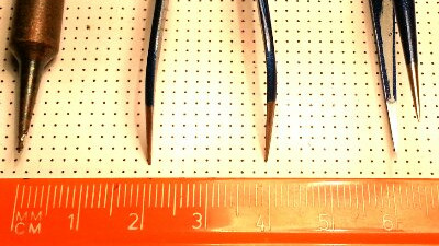
A fine point soldering iron tip, at first I tried with a 0.5mm tip on my iron, this is akin to digging up a pot plant with a JCB, it’s was far too big for the job. In the end I went for a 0.12mm bit, as you can see from the image below, this is pure copper. In order to keep the tip as pointed as possible, this is not coated with the protected coating normal bits are, and as such will take more care if it is to last.
-
A pair of fine point tweezers (straight, angled, or as I did, both), at first, I had tried by using a pair of long nose pliers (also known as needle nose pliers), if you thought the JCB was too big for the plant pot, the pliers here were something closer to lighting a candle using the death star. I inevitably succeeded, functionally, without the correct tools, but the result was far from elegant, and took significantly longer to get done, with of course, some damage to the surroundings in the process.
-
Double sided sticky tape, yes, really. It also just came to me that perhaps blue/white or any-other-colour-tac might also do the job, but I am yet to test this myself. More on this later.
Preparation
-
Lots of light, you can never have too much light, in my case I use a (directional) desk lamp pointing straight at my working area.
-
A clean, expansive work area, where you can find your tiny components, if they were to fly off as you try to fit them in place. As you can see from my photo above, I tend to keep some 2mm dotted white paper beneath my soldering mat, it comes in handy for sketching out circuits etc, and the main reason it’s there is because my desk is glass, which is not fun to work on, so this just makes it easier on the eyes.
-
Double sided sticky tape;
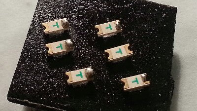
Surface mount components are tiny, and and of course very light. If you start poking one with a soldering iron, it’s going to run rings around your circuit board, or in fact your desk. In my effort to solve the issue, I came across this little nugget; A piece of double sided sticky tape, stuck to the desk, will keep your tiny components put while you prime them with solder, what’s more, I found an extra bonus, because it will indicate if you are applying a little too much heat to your tiny little friends, as the plastic based tape will quickly begin to melt, making a nice sticky mess. After a few goes, I had gotten to the point where I was no longer melting the tape, which means less heat to worry about frying my nice little components. It’s all about timing.
Once the new components are primed, it’s time to prepare the PCB. In this case I’m using matrix board/vero board, I planned out with a pen where I was planning to put the components, but with a properly made PCB, this will be more clear as there are pads, ready to place the components, usually marked too.
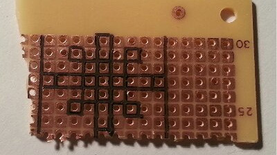
Once marked, the circuit board is ready to be primed. It’s a big help to ensure both sides of any solder joint (i.e. components and PCB, or PCB and wire, etc) are soldered, tinned, primed, however you want refer to it, but when surface mount soldering, it is all but essential. This simple preparation means less time taken working the solder joint, and less time means less heat transferred, meaning less chance of heat damage to your components.
Soldering
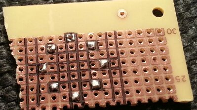
Now the board and components are ready, its time to start soldering. Using the tweezers, place the primed end of the components over the pre-soldered pad and touch the soldering iron to it briefly, just long enough for the solder to melt, taking care not to use too much solder, and not to keep the iron there too long, so the component isn’t damaged. Move both the iron and the solder away, and leave the joint to cool, don’t blow, because forcibly cooling a solder joint will only weaken it. The slower it cools the better.
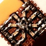
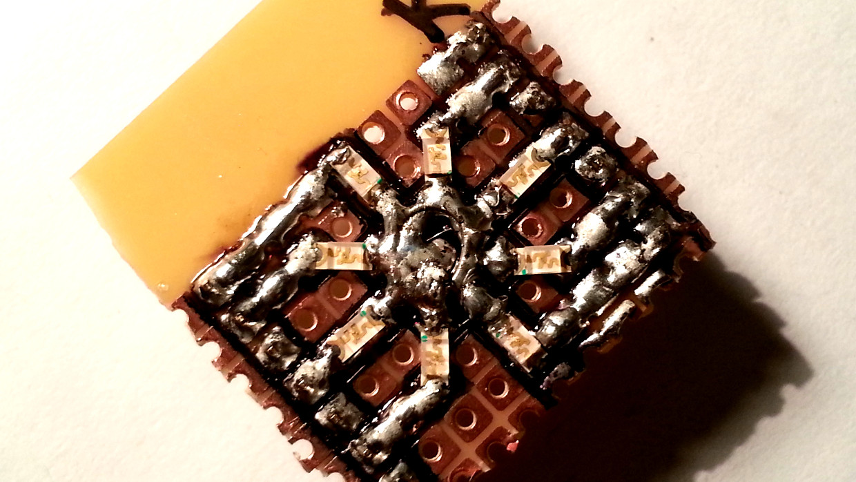
Here you can see the outer edge of each of the LEDs has been soldered. This ring is on its way to becoming an 8 LED common cathode ring. Once the outer contact is soldered, they aren’t going to move, making the rest of the job much, much easier.
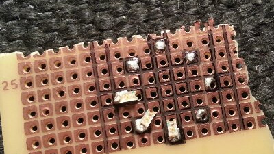
Having successfully completed the outer ring, is was now time to solder the negative leads of each LED, in this case, they will all be joined together (common cathode), I first soldered them to the board, and then took a piece of sold-core wire and removed the sleeving, bent it into a ring and soldered that into the middle as a sort of circular rail. On my first attempt, I had tried to fill the central spot with as much solder as possible, this was not a good idea, trust me.
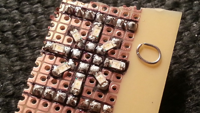
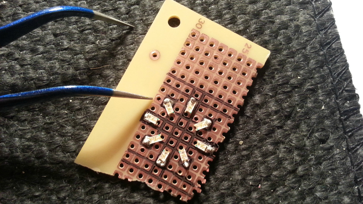
Now, finally, another key part I got wrong the first time, are the pins. The idea for my ring of LEDs, was to make it into a Dual in Line (DIL) style package, unfortunately, first time, I used the wrong tools for the job (Sorry Dad), forcing “vero pins” through the board, having soldered and finished the job, the subsequent forcing of these pins into a proto-board served nothing more than to rip the small pads of copper from the board, along with the LEDs soldered to them. Vero pins were not the right tool for the job!
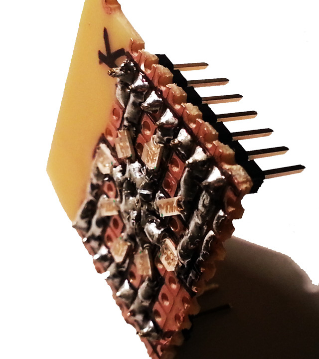
Header pins, were the right tool for the job, easily soldered on, they allow the whole thing to stand ever so slightly off the board and they fit nicely into the various type of header socket and proto-board holes. Further, I connected up the central, common cathode to the pin marked K, via a single resistor, meaning the whole board is already protected.
Done
So there we go, surface mount soldering isn’t too hard, the bad news, is that they were the largest (1206) of the SMD series of device sizes, and arguably the easier to solder. Next I’m waiting on some SOP->DIL adapters so I can mount some LM74 (I2C bus Temperature Sensors) for breadboard experiments with the Raspberry Pi. I might post a second part to this Tips & Tricks depending on what I learn when I get round to that.